Today I will be writing about a problem that has occurred a few times in my day job that seems to trip a lot of people up.
The disappearance of additional storage drives in an AWS instance running Windows Server 2012 R2.
Servers at risk
Windows Servers originally built from a AWS Windows Server 2012 R2 AMI prior to September 10th 2014.
Windows Servers built from a user built AMI that was originally created from an AWS Windows Server 2012 R2 AMI prior to September 10th 2014
Symptoms
Typical list of symptoms of this issue include:
Sudden disappearance of additional drive/s after a shutdown or reboot;
Despite the drives no longer appearing in Windows you will see the drives still attached in AWS.
Attempts to un-mount the drives and remounting them (even to new mount paths) will result in no fix.
Loss of custom IP configurations in your Ethernet adapters on the server (such as static IPs, gateway and DNS settings / values, as well as the re-enabling of ipV6 if you had turned this off previously). Note: If this happens depending on your AWS setup you may be unable to even access this server. See the “regaining access to your server” section at the end of this page.
Cause
In short the issue is caused by the “Windows scheduler plug and play clean up” and will impact any Windows Server 2012 R2 AMI release before September 10th 2014.
Fixing this is a two stage process, first we need to reinstall the XenTools drivers for the AWS server, then we will need to run a script file that AWS has published to disable the scheduled task that causes this mischief-ery.
Reinstalling the ZenTools drivers
When I originally had this problem the gentleman at AWS recommended that I reinstall the ZenTools drivers, so I will recommend the same to you now! 🙂
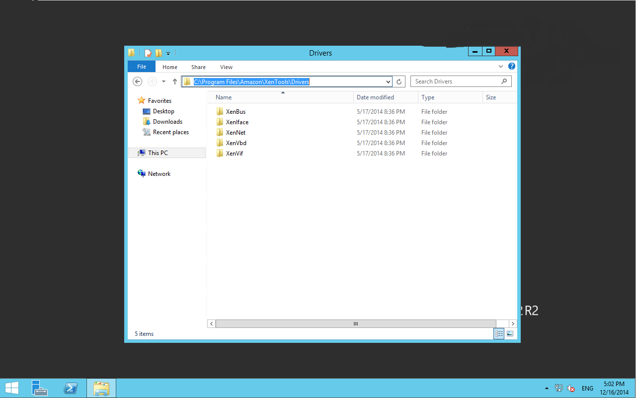
The drivers for re-installation should be located on your server at: C:\Program Files\Amazon\XenTools\Drivers\
The location for your XenTools drivers should be C:\Program Files\Amazon\XenTools\Drivers
Then make your way through the folders reinstalling the drivers below (right click the files in the list below and select “Install Driver”)
If you check now, your drives have probably re-appeared. If not don’t panic they will later, and if they have DO NOT STOP HERE, you need to do the next step as well or this could happen all over again.
Download this onto the server and extract to a folder close to the root of c:, for this example we will be placing the RemediateDriverIssue.ps1 file in the folder c:\temp Please adjust the command below as necessary to suit your situation
Start a Power Shell as “Administrator” WARNING! Do not start a Power Shell ISE to run this script! Use a regular Power Shell running as Administrator.
Execute the following command into the power shell, remembering to adjust the path to where you placed your script file as necessary:
Inspect the on screen feedback, you should be met with a success message shortly. Go ahead and close the window at this point. You’re done!
If you don’t get any success of if the script identifies that it is not suited to your situation follow the onscreen prompts. If you need help contact AWS support and advise them of this page so they know what you have attempted. Alternatively post below and maybe I can help.
You’re Done!
And that’s it! Your drives should now have reappeared and your patch / script should now be applied to prevent this from happening again. However the last thing to do is reboot the server to make sure that our fix will stick. If your server still has issues after this, post a comment below and I will try to help!
Oh and if you keep regular backups or AMIs of your servers, make sure that you create new ones of them now so you don’t have to reapply this fix again to your future instances!
Regaining access to your server after a loss of custom networking settings
This is not a fun situation to be in, however you may get lucky. Below is a list of things you can try depending on your circumstances and network configuration.
I have access to another server attached to the same VPC / Subnet
Ok this is great, here is what you can try:
Make sure that RDP is enabled on your security groups that both the server you want to be able to reach and the server you can reach are attached to.
Reboot the server that you are unable to reach (gracefully if possible) from the AWS console.
Once the server is back online, wait for the server health checks to complete.
Look at the details of that instance and locate the AWS DHCP assigned ip address
On the server you have access to, attempt to establish a RDP session to the IP Address you observed in the previous step.
Hopefully you should have established a connection to the server.
I don’t have another instance on the same VPC / Subnet, but I can create a new instance
This isn’t a bad option. Essentially all you have to do is create any old Windows server on the same VPC, then do the previous suggestion. Once complete you can delete the instance you just created. Should only cost you a couple dollars and will give you access again to the server.
I don’t have another instance on the same VPC / Subnet, and I cannot create a new instance
This isn’t too bad either, try the following:
Create a new network adapter for the server in a VPC with a security group that allows RDP.
Attach that network adapter to the server you want to be able to access.
Assign yourself a new Elastic IP and attach it to the new network adapter.
Attempt to establish a remote desktop connection to the server.
I cannot do any of the above, or the above did not work for me and I still cannot access my server
It’s time to contact AWS support unfortunately, you can also try posting below and I or someone else that trolls this site may be able to offer assistance. Don’t forget sites like Server Fault too as they are full of geniuses and always yield quick responses. Just be sure to keep the community happy by writing whilst not in a panic and in detail, and most importantly always Google first.
In this tutorial I am going to show you how to create a WiFi Relay using your Raspberry Pi. This will allow your Raspberry Pi to connect to a Wifi AP and then also broadcast it’s own WiFi, and route that traffic over the original WiFi AP.
Raspberry Pi Wifi Relay
So why would you want to do this?
So you may be wondering “Why would I want to relay wifi”, well there are lots of legitimate and admittedly illegitimate reasons for doing so. My purpose for making this myself was for a work reason. Our company issues us consultants with a 4G dongle (a ZTE MF821) per client site. The ZTE MF821 has wifi capabilities built in however it only allows for 5 connections at most at any time, which really doesn’t work when you’re working on a project that has a full compliment of staff working and needing internet access. So I needed a way to relay this internet connectivity on a new AP that didn’t have the limitation of 5 devices. And that’s my Raspberry Pi.
To make it an even cooler solution, I decided to impersonate the WiFi back at our head office. And because every consultant has the company WiFi already stored in our devices, as soon as a colleague walks onto client site, they are instantly connected. Very Cool!
So let’s begin!
What you will need to do this tutorial:
Raspberry Pi Model B+
A Raspberry Pi (of course!)
Either the Model B or B+ is perfect for the task, but don’t overclock it, it’s unnecessary for this task.
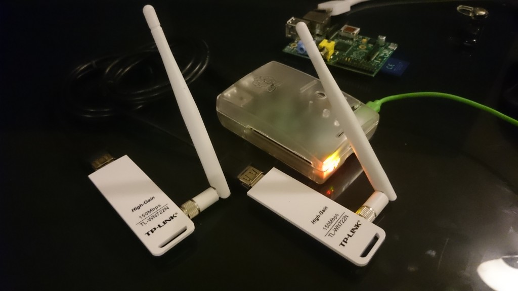
TP-Link WN722N Adapters
2x WiFi adapters that are linux compatible
I highly recommend using TP-Link WN722N, they are awesome adapters and compatible with nearly anything. However if you haven’t got one of these and need to find an adapter that will work, google “Kali WiFi Adapters” and you will find lists of highly compatible devices to buy.
Samsung 16GB Micro SD
A fresh Raspbian on a SD / Micro SD card ready to go!
I will be using the Raspbian Wheezy 2014-09-09 release during this tutorial. Make sure you have completed the Raspbian config utility prior to starting this guide.
Assumptions:
This guide will assume that:
You have completed the Raspbian Setup Utility
You are connected to your raspberry Pi and can create a shell session either by eth0 or a console cable. Warning! if you connect via WiFi it could affect your ability to do this tutorial successfully.
We will be using nano as a editor in this tutorial, and putty as a shell. Vim people – don’t be haters 🙂 and mac users can use the ssh command in your terminal in lieu of having putty.
You have a working understanding of setting up a WiFi network using a retail piece of equipment.
You have a working understanding of basic network configuration (DHCP servers and clients, IP addressing, subnets and routing)
You have a working understanding of the basics of linux, such as editing files, traversing the file system and using basic applications.
Okay, let’s begin!
So the first thing we will do is make sure our Pi and it’s packages are updated:
apt-get update -y
Now we need to grab all the packages we will be using for this process:
Once this completes it’s time to setup our hosted AP.
Part 1 – Setup the Raspberry Pi WiFi AP
Editing /etc/network/interfaces
The first thing we need to do is attach a wifi adapter to become wlan0, so go ahead and do it now. It may take up to 30 seconds for the devices to fully install and register. To see if this is completed keep running ‘iwconfig‘ until you see wlan0 appear.
Now we need to configure our new network. We will be using wlan0 for the Raspberry Pi’s WiFi AP and wlan1 later as the client of the existing WiFi AP. You can use a different IP Address range and subnet if you wish but we will be using 192.168.10.0 / 255.255.255.0 for this tutorial for our hosted AP and issued DHCP leases.
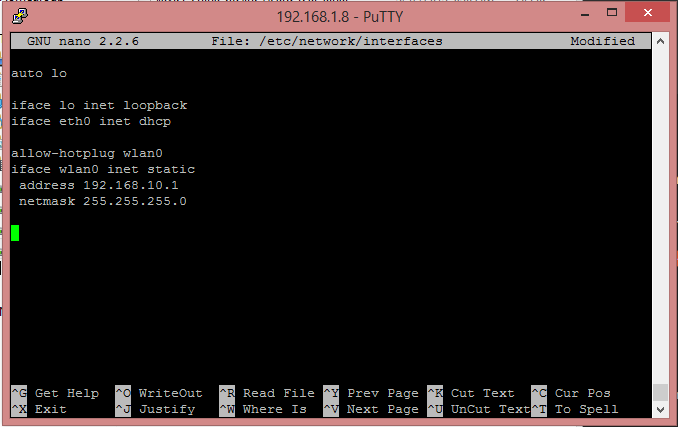
Let’s edit /etc/network/interfaces and setup the correct configuration for our adapter. We need to make sure that our wlan0 is configured with static ip addressing on the correct subnet rather than the default conf which is occasionally loaded by the OS (don’t panic if all you see is the first three lines of the screenshot, just append to the end of the file.) Start the editor by running the following command:
nano /etc/network/interfaces
Now remove the preexisting configurations in this file in reference to wlan0 and then append the following to the end of the file:
This is how your /etc/network/interfaces file should look at this stage, we will be editing it more later!
Hit Ctrl+X and press Y to save and exit nano.
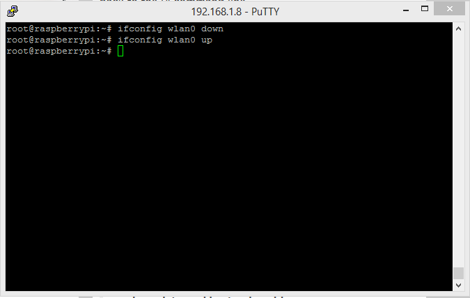
To confirm that your file is configured in a ‘sane’ way, lets bring down the adapter and put it back up again by running the following two commands:
ifconfig wlan0 down
ifconfig wlan0 up
If there is an error in our configuration then you will see output when you try to put the adapter back up. However I am sure yours will look just like mine does below:
If your conf is good, your output should be the same as the above
Configure DHCP – Editing /etc/dnsmasq.conf
OK now that our network adapter wlan0 is statically configured, we need to configure dnsmasq. The config file for this is HUGE! you will have to make use of the search in nano (Ctrl+W, type string to search for and hit enter. to repeat a search press Ctrl+W and then hit enter).
Edit /etc/dnsmasq.conf by running the below command:
nano /etc/dnsmasq.conf
The make the following adjustments:
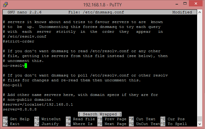
Search for #no-resolv, remove the leading # to uncomment this line
Make sure your line looks like this
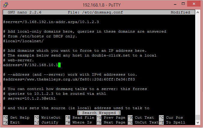
Search for #address= and change this line to be: address=/#/192.168.10.1
Make sure your line looks like this
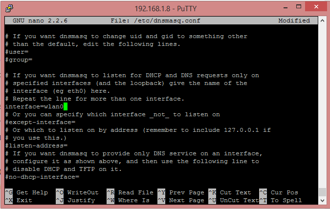
Search for #interface= and remove the leading hash to uncomment the line, and then add wlan0 after the = sign.
Make sure your line looks like this
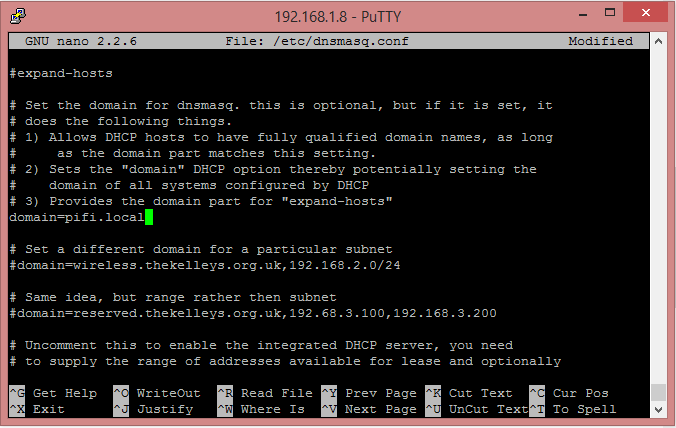
Search for #domain= remove the leading hash and then change it’s value to pifi.local (or whatever else you would like).
Make sure your line looks like this
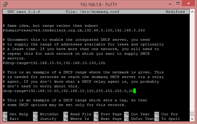
Search for #dhcp-range and remove the leading hash, then change the line to read: dhcp-range=192.168.10.50,192.168.10.150,255.255.255.0,2h
Make sure your line looks like this
Hit Ctrl+X and press Y to save and exit nano.
That’s the worst part of the configuration sorted for this tutorial. The other config files are a lot easier to deal with I promise.
Configure hostapd – /etc/hostapd/hostapd.conf
OK now we need to configure our WiFi AP that our Raspberry Pi will be broadcasting for our clients to connect to.
Edit /etc/hostapd/hostapd.conf by running the following:
nano /etc/hostapd/hostapd.conf
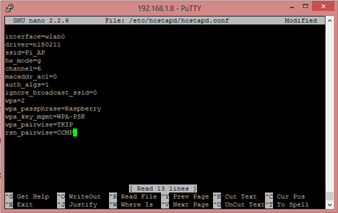
Erasing anything that is pre-existing in this file, paste in the below configuration whilst changing the values for ssid and wpa_passphrase to whatever you like.
Warning: You need to be extremely careful with the formatting of this file;
Wrap values with spaces in them with quotes “”
Ensure there is no leading or trailing white space on any line
Make sure there is no white space between the key=value elements
Make sure there are no blank / empty lines at the top or bottom of the file.
hostapd is very particular about what it likes to consume.
Once your config looks like the below….
Your hostapd file should look like this
Hit Ctrl+X and press Y to save and exit nano.
Now it’s time to test out our WiFi AP!
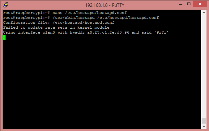
Run the following command to start hostapd and broadcasting your new AP.
/usr/sbin/hostapd /etc/hostapd/hostapd.conf
And you should see the following…
Your output should be similar to thisYour new PiFi should now be visible to devices
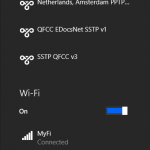
And if you check on a PC with wifi you will see your new WiFi AP being broadcasted!
If you now attempt to connect to the wireless AP using the credentials you set earlier then you should connect to the wifi, get a dchp lease and even be able to connect to your raspberry pi over it!
However for now we need to stop this wfi and continue with our configurations before we make it permanent, so go ahead and hit Ctrl+C to stop the wifi and regain control of your shell.
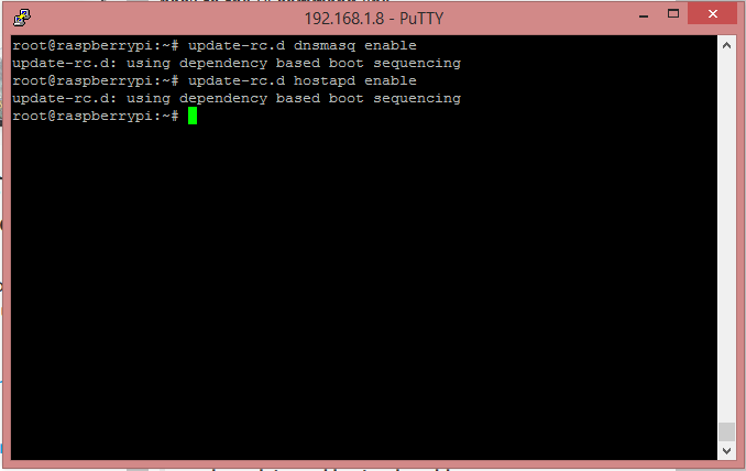
The last thing we will do is run a command to make sure that dnsmasq and hostapd will start at boot:
If your output looks like the above then dnsmasq and hostapd are all set to auto start when the pi boots!
Part 2 – Configure wlan1 to be a WiFi Client
Now you can connect your second WiFi adapter which will install and become wlan1, just as before you can keep running iwconfig until you see wlan1 come online.
Edit /etc/network/interfaces again
Open up /etc/network/interfaces using the following command:
nano /etc/network/interfaces
And below our settings for wlan0 with a empty line between for nice readability, enter the following configurations for wlan1
Open up /etc/wpa_supplicant/wpa_supplicant.conf using the below command:
nano /etc/wpa_supplicant/wpa_supplicant.conf
When you open this file you will probably see couple lines already populated, if so just edit the file to look like the below, otherwise paste the configuration below into the editor, and then change the settings as needed to the WiFi point you want wlan1 to be connected to.
ctrl_interface=DIR=/var/run/wpa_supplicant GROUP=netdev
update_config=1

network={
  ssid="YOURSSID"
  psk="YOURPASSWORD"
  # Key management type can be: WPA-PSK or WPA-EAP (Pre-Shared or Enterprise)
  key_mgmt=WPA-PSK
}
Once you have updated the configuration to match the above / your personal WiFi setup hit Ctrl+X and then press Y to save and exit nano.
Now it’s time to reboot your device, when it starts up it should try to connect to the WiFi point you set in here, run the following command to restart the pi:
reboot
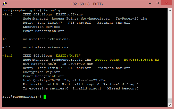
Once the pi starts up and you’re logged in again, you can confirm that the pi is connected to your WiFi on wlan1 by running the following command and looking at the data for wlan1:
iwconfig
You should see the following, just with your WiFi details:
Congrats! Your wifi client is now connected!
Routing traffic between wlan0 and wlan1
OK we now have a working WiFi AP on wlan0 which issues DHCP leases and we have a working WiFi client on wlan1 which can browse the other WiFi AP’s network (and presumably the internet). So now we need to rout traffic inbound to wlan0 to wlan1 and returning traffic from wlan1 to the requester on wlan0.
We do this in just two steps.
Enable IP Forwarding – /etc/sysctrl.conf
Open /etc/sysctrl.conf by running the below command:
nano /etc/sysctrl.conf
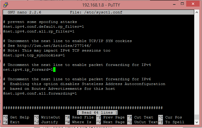
Search for “net.ipv4.ip_forward=” then remove the leading has symbol making sure your line looks like the below:
Make sure your line looks like the above.
Hit Ctrl+X and press Y to save and exit nano.
And because we want to save ourselves a reboot we will hot activate it for this boot by running the following:
sh -c "echo 1 > /proc/sys/net/ipv4/ip_forward"
Enter iptables rules to route traffic between the adapters wlan0 and wlan1
This is really simple, just send the following commands in the shell:
iptables -t nat -A POSTROUTING -o wlan0 -j MASQUERADE
iptables -A FORWARD -i wlan0 -o wlan1 -m state --state RELATED,ESTABLISHED -j ACCEPT
iptables -A FORWARD -i wlan1 -o wlan0 -j ACCEPT
Then we will save these routes to file to be loaded again when the server boots.
sh -c "iptables-save > /etc/iptables.ipv4.nat"
Lastly we need to edit /etc/network/interfaces one last time to add a command that will load these iptables rules when the server boots.
Open /etc/network/interfaces using the below command:
nano /etc/network/interfaces
And at the very end of the file append the following:
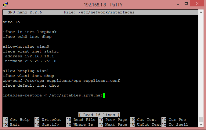
iptables-restore < /etc/iptables.ipv4.nat
If your configuration now looks like the below….
Make sure your conf looks like the above, keeping in mind your personal customizations to the network addressing scheme / subnet
Then press Ctrl+X and then press Y to save and exit nano.
That’s it! You’re all done!
Congratulations, you made it if you reboot your pi when it starts you should see in about 1 minute your wifi AP appear and if you connect to it, you should be routed from wlan0 to wlan1 and out to the other WiFi AP.
In my introduction I mentioned that in my real world application of this setup I am pretending to be a WiFi AP in another location. To achieve this yourself all you need to do is configure your hostapd file (/etc/hostapd.conf) to the same settings as the original AP, then when devices walk in rage of your WiFi AP it will connect to it perfectly.
Where to now?
Well you could:
See if you can apply the above logic to create a WiFi AP for eth0.
Create a VPN client connection on your Raspberry Pi and route wlan0 out that effectively creating a secure VPN WiFi AP.
Test your dark side and sniff traffic going between wlan0 and wlan1 (for this use the Kali distro for Raspberry Pi as a base).
Create a mesh of roam-able WiFi points all around your house and in your back yard.